
Le phénomène Drascombe
Article paru dans le numéro 149 du "Chasse-marée"


Building Kurbatov's 'Paltus'
Translated from the Russian ....
The attention of amateur boatbuilders is drawn to the proposed project, which
has been developed from the sales materials of Honnor Marine, builder of the
Drascombe series of boats. By careful study of this project, a real possibility
exists for the home builder, using readily available materials.
The hull is sheathed using strips of 7mm thick waterproof plywood (1),
using the 'edge-upon-edge' or clinker method. Plywood is also used in the
construction of frames, onboard seats and deck. During construction, the strakes
are glued together and rivetted with 3mm copper nails/rivets and copper washers
at 60-80mm intervals. The double-thickness clinker overlap (which should be
within the limits of 15-20 mm) serve as longitudinal stiffening stringers which
makes possible the construction of a strong and rigid hull with the additional
use of only five frames. Even further strength and rigidity are provided by the
vertical walls and horizontal surfaces of seating and decks.
1. The '7mm waterproof plywood' to which Kurbatov refers is a special grade
available in Russia. If using WBP or marine plywood, then the next size up
should be used.
Another, more contemporary method of building the hull with the same "angular"
contours is proposed: the strakes may be joined by clips made from copper wire,
with epoxy resin and glass tape being applied to both sides of the join. The
copper clips only provide a convenient method of assembly, the ultimate strength
of the join being dependant upon the epoxy and glass fibre tape. One Leningrad
boatbuilder has even employed synthetic thread in place of the copper wire in
the construction of an 8-metre plywood yacht.
Both methods of construction are approximately equivalent in terms of labour,
expense and reliability. However, many supporters of clinker construction
consider that their method deflects spray and helps to moderate rolling in heavy
sea. One criticism made of the 'stitch and tape' method, however, is that if the
gluing of the fibreglass tape is inadequate, moisture penetration with rapid
rotting of the wood may follow. Thus it is necessary to ensure that the seams
are covered adequately on both sides with glass tape (using several layers -
see later) and epoxy glue.
Assembly of the hull may be more conveniently performed on the construction mold
in the normal position, i.e., with the keel downwards. The strakes are then
applied to the previously assembled and carefully positioned transverse frames,
keel, stem and transom. When constructing the mould, the dimensions of frames 2,
4, 6 and 8 (as taken from the table of offsets) must be adjusted to take into
account the thickness of the external plywood skin, as the measurements given
refer to the external hull surface. Within the table, measurements of the chines
are considered to be that of the upper edge of the strake.

|
Table
of Offsets |
Frame Number |
|||||||||||
|
0 |
1 |
3 |
3 |
4 |
5 |
6 |
7 |
8 |
9 |
10 |
Tr. |
|
|
Height from the Base-Line, mm |
||||||||||||
|
Keel |
260 |
61 |
10 |
0 |
7 |
25 |
51 |
88 |
128 |
173 |
221 |
- |
|
Strake 1 |
355 |
300 |
250 |
215 |
186 |
176 |
179 |
190 |
210 |
235 |
263 |
265 |
|
Strake 2 |
520 |
456 |
405 |
360 |
325 |
310 |
310 |
324 |
348 |
378 |
405 |
415 |
|
Strake 3 |
740 |
680 |
624 |
580 |
550 |
530 |
522 |
534 |
560 |
593 |
628 |
667 |
|
Sheer |
965 |
910 |
864 |
825 |
792 |
778 |
762 |
760 |
760 |
770 |
780 |
- |
|
Half-widths from centre-line, mm |
||||||||||||
|
Sheer |
286 |
510 |
689 |
820 |
900 |
945 |
955 |
932 |
880 |
795 |
685 |
545 |
|
Strake 3 |
230 |
466 |
655 |
800 |
895 |
945 |
955 |
932 |
880 |
765 |
685 |
545 |
|
Strake 2 |
140 |
363 |
551 |
699 |
795 |
848 |
860 |
838 |
784 |
705 |
608 |
555 |
|
Strake 1 |
52 |
225 |
380 |
510 |
605 |
660 |
671 |
649 |
595 |
514 |
415 |
- |
The stem and keel must be faired before attaching them to the building mould:
the stem-piece should be bevelled to accommodate the bunching together of the
strakes where they will join the stem. The required angle can be determined
either by a lath or a length of the plywood used for the strakes.
Before cutting a strake from a plywood sheet, a full-length template should be
made from low-quality plywood or hardboard. After attaching the template to the
curved mould by panel-pins, the lines of the strake are extended outwards from
the mould and marks made on the inside of the template. After removing the
template, these marks may be joined by using a flexible lath to indicate the
position of the next strake. (With the exception of the sheer-strake, an
allowance of 15-20mm should be added for overlap. Then place this template onto
the high-quality plywood to be used for the strake, and transfer the line by
pricking-through with the point of an awl, before finally cutting-out the
strake.
The first strake to be applied is the lower bottom, and is attached to the keel
by 4mm x 30mm wood screws, spaced at 60 mm intervals. At the stern, the next
strake will present at an abrupt angle which makes the overlap unsuitable for
riveting. Here it is better to simply butt it's edge against the previous strake
and secure with copper wire clips and epoxy and glassfibre tape as described
above, after trimming to ensure that the strake fits snugly against the bottom
strake. The adjoining edge surfaces are thoroughly cleaned, and coated with glue
before rivetting.
The longitudinal clinker strakes must become flush at the stem. Thus for a
distance of approximately 800 mm it is necessary to chamfer the outer edge of
the strake and the lower inner edge of the next strake of the clinker join.
The strakes are temporarily attached to the
mould by
nails, so that when the entire hull is riveted, the moulds may be taken out and
replaced by frames, with wood screws being employed to secure the skin to the
frames, using the nail holes as a guide. Rather than fairing each frame so that
the planking will have flat surfaces to glue and fasten to, installation of the
frames may be simplified by bevelling only those frame components which make
contact with the inner surface of hull (i.e. the frame battens) to provide a
flat contact surface - then the plywood frame itself may be attached to those
previously bevelled parts, directly into place.(2)
To further simplify this process, the hull can be pulled gently away from the
mould using suitable lengths of wood. It is necessary to have previously made
cut-outs in the frames for the longitudinal chines of the strakes.
2. Taking 'Frame - Station 2' as an example (see
Frames diagram),
cut the plywood frame with a flat (90 degree) edge. Then cut wooden battens 58
and 51, and bevel them to fit the hull curvature, before attaching them to both
the hull and plywood frame with screws and glue. Then cut-out and attach batten
60. The frame is now completely installed into the hull.
The described boat uses a heavy centreboard, cut from steel plate of thickness
12 - 14 mm. It's weight is about 45 kg which, when added to the dynamic loads of
landing on a sand-bar or even simply when rolling, requires a centreboard case
of substantial strength. The base, knees and supporting timbers of the
centreboard case should be made from oak, with the walls of the case being made
from 7 - 10mm exterior plywood, the case being secured to the keel by bolts,
with waterproof glue being used throughout. A second similar well, in a smaller
size, is provided for a lifting rudder. Before assembly, a layer of diluted glue
should be applied to the internal surfaces of both wells, as a sealing coat.
In spite of the high water resistance of exterior plywood, it's open edges
require protection against the penetration of moisture. Two or three layers of
fibreglass tape with a width of 25-40mm should be laid on all outer edges, with
a wider overlapping layer superimposed upon these. Covering the joins using just
one piece is not an option, as voids may be created along the angles, into which
water will subsequently penetrate.
For rowing, the boat must be fitted with a pair of removeable transverse thwarts
(with the sizes 28 x 250 x 1200 mm), which would be located above the
longitudinal bank-seats and prevented from moving along the boat by simple
bosses or lugs attached to boards at their leading and trailing edges. The
optimum length of oars for this boat is 3300 mm. (10'10")
The unsinkability of the boat may be assured by providing hermetic sealing of
compartments beneath the longitudinal bank-seats (for example between stations 4
and 6), although it would be necessary to provide hermetically-sealed inspection
holes in the vertical walls of the compartments for their periodic inspection,
repair and drying. Alternatively, the area beneath the bank-seats could be
filled with closed-cell foam buoyancy.
Anticipating questions from readers as to what opportunities exist for the
substitution of waterproof plywood by other materials, we shall answer as
follows:
for the building of this boat it is possible to use a sheet
glass-fiber-reinforced plastic, fiberglass laminate and even the more usual
construction-grade plywood, providing that several layers of fiberglass fabric
are applied on top of the skin in order to achieve the desired rigidity and
durability. A thickness of GRP skin of 4-5 mm would be sufficient, especially if
reinforced by ribs made from plastic foam. Even if these materials are not
available, it would still be possible to build the hull from glued strip-plank
laths, or even fir or pine boards, glued edge to edge.
The main-mast, mizzen and gunter spars are of continuous, round cross-section,
however it is preferred that these be made from two or even four pine laths, as
glued spars are more durable and there is less chance of them warping with
fluctuations of humidity.
Regarding the sails
and rigging of
the boat: the mizzen-mast has no standing rigging - it stands in a metal mast
step, and is supported by wooden partners at the top of the rudder well. The
mainmast is supported by a pair of shrouds, and a forestay - which can be
provided by the steel luff-wire 'bolt-rope' of the foresail if jib
roller-furling is fitted. This roller-furlingconsists
of a drum (6), attached to the tack of the jib or genoa, being freely rotating
relative to it's deck fitting (10). The head of the sail is attached to the
halyard by means of a swivel (2), which ensures free rotation of the foresail's
luff-wire or bolt-rope without twisting the halyard. Thin synthetic rope (7) is
wound on the drum, so that when it is unwound the foresail is reduced to a dense
roll.
The running end of this control rope (7) is led back into the cockpit for ease
of access by the helmsman.
Thus, at anchor, or at the approach to land, it is not necessary to lower the
sail from it's mast. To restore the sail to it's working state, all that is
required is to release the control rope, and unfurl the sail by pulling on it's
sheets. Of course it is still possible to attach the foresail in the usual way,
using piston-hanks or clips hooked onto the forestay.
The mizzensail-boomkin must be made detachable; for it will simplify mooring by
the stern to a high quay and simplify management of the boat when sails are not
being used.
Installation of the main-sheet of the "Paltus" may be the same as on the
original "Drascombe Lugger", when it is possible to control the sail by means of
one sheet, and during tacking it is not necessary to adjust the sheet with each
turn - the sail automatically passing from side to side, although it is
recommended that the sheet's cleat be positioned close to the centreline so that
on both tacks the sheet length is approximately equal.
The Drascombe® Lugger
Translated from the Russian ....
These open boats can be found in large numbers in almost in any sailing centre
around the coast of England and on large lakes and rivers inside the country.
Quite often "Drascombes" can be found at sea far from the coast, where they cope
well on steep waves, maneuvering under their characteristic low-aspect sails.
The firm "McNulty Boats" have produced five models of glass-fibre "Drascombe"
boat, differing only slightly from the original "Drascombe Lugger" (1964). The
secret of the success and popularity of a boat of this type can be found in a
design which ensures a high level of seaworthiness, an attractive appearance,
high quality manufacturing, and unpretentiousness in operation: in simplicity of
the control of sails and efficiency when navigating under low power engines.
|
LOA, m |
5.7 |
|
LWL, m |
4.6 |
|
Beam max, m |
1.91 |
|
Beam, laden waterline, m |
1.52 |
|
Draft, board up, m |
0.26 |
|
Draft, board down, m |
1.2 |
|
Dry weight with rigging, kg |
380 |
|
Waterline displacement, kg |
550 |
|
Sail Area, m2 |
12.3 |
|
Power of outboard motor, HP. |
3-8 |
|
Speed with a 5HP motor, km/h |
11 |
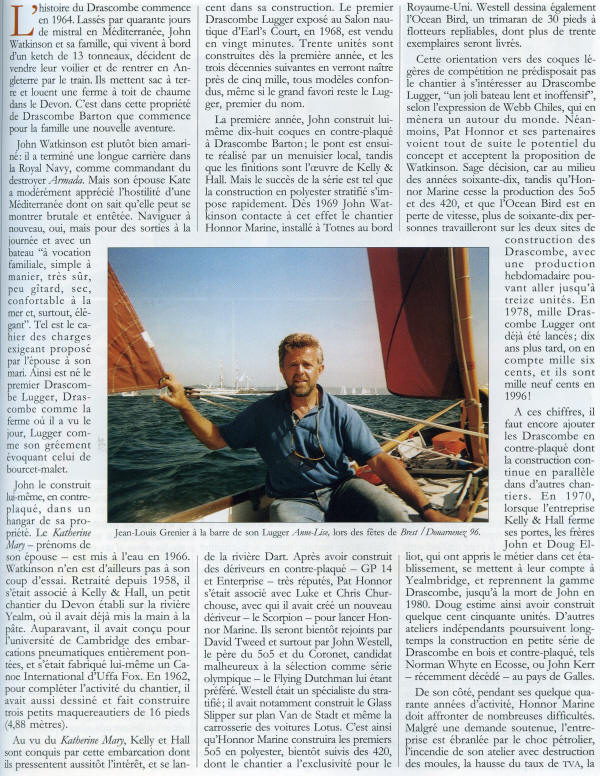
The Drascombe® Lugger
This boat was developed in 1964 by the former owner of the Totnes shipyard and
former Royal Navy officer John Watkinson, when he decided to leave small
shipbuilding and study agriculture at his farm on Dartmoor. But John could not
completely say goodbye to the sea and soon he began to think about building a
boat for himself and his family for day trips and fishing. The future vessel had
to be capacious - large enough to carry the whole Watkinson family - stable,
seaworthy, easy to control, and to have comparatively low weight so that it
would be possible to transport it on a trailer behind a family-sized car.
Furthermore, John wanted the boat to be capable of giving an experienced sailor
a lively and exciting sail, and to develop sufficient speed with the outboard
motor to overcome the flow of the river Dart.
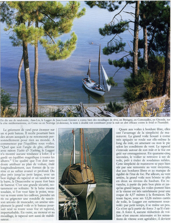
In 1965 the "Drascombe Lugger", as the designer named his creation, was
successfully launched in the river Dart and it successfully underwent further
trials in the estuary (the mouth of which is subject to strong seas and tidal
currents) and in the adjacent coastal waters of Southern England. As Watkinson
did not intend to enter into mass production, the hull was of wooden
construction, the lines of which were inspired by the coble working boats of
England's North-East coast, which themselves can trace an ancestry back to the
Vikings.
The boat that John hand-built in a barn on his farm at Drascombe Barton was an
immediate success and its obvious commercial potential prompted him to initiate
production of the boats in GRP. Other models followed, but all followed the
original philosophy of safety, robustness, and fun.
The hull of the first boat had a length of 5.72 m with a beam of 1.9 m and
formed from strips of 9 mm waterproof plywood, with 4 planks on each side, so in
appearance it resembled the clinker construction of the original working boats.
Inside the perimeter of the hull were fixed wide longitudinal bank-seats,
imparting extra rigidity in combination with several frames, which are also made
from water-resistant plywood. These bank-seats proved to be very convenient for
the counterbalancing of the boat when sailing, with crew leaning back against
the support of the bulwarks.
The designer has provided opening-scuppers in the boards at seat level for the
draining of water. If the "Lugger" should ship a wave or should it become
necessary to put the boat on an even keel after capsizing, water above the seats
will drain outboard, with the bulwarks remaining above water level. Spaces under
the bank-seats were filled with blocks of foam plastic, which ensured
unsinkability. This cockpit arrangement provides sufficient accomodation for 4-6
people on a short trip, together with the necessary equipment for a more
prolonged journey.
The boat was fitted with a heavy centre-board, cut from 13 mm steel sheet. It
weighed 55 kg, and when lowered increased the draft to 1.22 m, noticeably
increasing the stability of the vessel. The rudder blade was made from 4 mm
steel plate, welded to the rudder head and, as with the centre-board, it
descended into it's own well. In shoal waters it was possible to lift the rudder
and steer the boat with the aid of a steering oar, for which a special recess
was provided in the transom. The draft with the plates lifted did not exceed
0.26 m.
A third well was made in the transom for an outboard engine. The engine sits
within that housing and is thus protected from wave damage from over the stern.
In the case of a breakdown at sea it is possible to repair the engine without
hanging out over the transom., and when sailing the engine can be tilted back
with it's propellor clear of the water, so avoiding drag.
The boat was equipped with a triangular foresail, mizzensail and mainsail with a
total area of 12.26 m2. The solid section masts were made from glued laths: the
mizzen-mast having no standing rigging (the area of the mizzensail being only
2.04 m2 ), but the mainmast is supported by a forestay and a pair of shrouds.
This "one-and-a-half- mast" arrangement is very convenient for trolling for
fish, as under just foresail (3.34 m2 ) and mizzensail the boat can head into
the wind at low speed, or stably drift. The mizzensail also proves to be useful
during navigation under engine, or when lying at anchor when it holds the bow
into the wind and waves, thus decreasing the rolling motion.
The sails were boom-less, simplifying their control by unskilled crew. It is no
longer necessary to fear being struck on the head by the boom during tacking.
Likewise, gybing is less dramatic. With a boom, the sail moves sharply across
the boat with it's dynamic force being transferred to the mast and rigging, a
process which is sometimes accompanied by an overturning of the boat, but the
boom-less mainsail will move from board to board without this dynamic force.
This is familiar to every yachtsman who has had to change a mainsail or trysail
in a storm.
The luffs of the main and mizzensail are laced to, and may be kept furled around
their masts. The foresail was also fitted with a roller-furling mechanism to
roll the sail around the forestay. In order to get under way using sails, it is
sufficient to release the canvas on both masts, and the vessel is ready.
Likewise, not more than three minutes are required to douse the sails - it is
even possible to remove the masts with the sails still attached to them, which
can then lie within the boat. The mizzensail is sheeted via a boomkin.
The Drascombe Lugger has proved to be an ideal family boat - a day sailer for
navigation in the rough coastal waters around England. It was very stable, and
in response to sudden squalls the "Lugger" heeled only to the level of the
scuppers - heeling did not increase even during further strengthening of the
wind - thanks to the wide beam, heavy centreboard, and low sail area. With a 6HP
outboard engine the boat developed a speed of 5.5 knots (10 km/hr), although
being light it is also easy to row, especially with one person on each oar.
The hull is built from 9mm
marine plywood. The frames, bulkheads, centreboard case and rudder trunk are
made from 12mm marine plywood. It is recommended that Iroko hardwood be used for
floors, gunwales, frame doublers and stem laminates. The decks are made from 6mm
marine plywood, and the masts and spars are made from Columbian Pine or Douglas
Fir, as is the inwale, to achieve a fair curve at deck level.
The forward bulkhead, midship
frames, aft bulkhead, transom, centreplate case, rudder trunk and outboard motor
well are all pre-cut and reinforced with hardwood or marine plywood doublers at
various points, and assembled prior to fastening them to the building jig.
The rudder trunk is glued and
fastened to the aft bulkhead and transom along with the outboard motor well, and
the centreplate case is glued and fastened to the midship frames. The components
are then fastened to the building jig using temporary fastenings. The hull is
built upside down on the building jig.
The frames are then tied
together with an inwale at deck level and a hog and inner stem laminates. The
fair-up of the frames then takes place and the wide garboard plank is fitted.
The next stage is to plane the
plank land to create a joint surface for the next plank, it is vitally important
that the joints are accurate, because the hull has very few fastening in it when
finished, and you cannot edge-set a plywood plank as you would a normal timber
plank.
The next plank when dry fitted is then pre-drilled to take small diameter bolts
at approx. 6 inch spacing, these acting as a temporary clamping system,
fastening the planks together until the glued joints have cured. The whole of
the boat is of glued construction using phenolic resin glues such as Aerodux 500
or Cascophen. The bolts are removed at a later stage. The procedure is similar
for the next plank.
The hull is now built to deck
level and a general fair up takes place, prior to fitting the keelson and the
outer stem laminates. The outer stem laminates are glued together using 3inch x
½ inch coach screws with wooden pads to spread the load; they are screwed
through the pre-drilled laminates into the inner stem laminates that were fitted
before any planking was added. When the glue has fully cured, the bolts and
coach screws are removed and hardwood dowels glued in their holes to give a
complete solid wood construction for all of the joints and very few fastenings
in the hull at all.
The build has now reached the
point at which the outside of the hull can be faired up and an almost complete
finish achieved, even though the boat is only built to deck level with just 3
planks. The hull can now be released from the building jig and turned the right
way up. The process to completion can begin with a clean up of the inside of the
hull, cutting off all of the hardwood dowels which make the boat look like an
inverted porcupine, cleaning up any glue excess and fitting the deck beam,
carlands and ancillary reinforcing blocks.
The next stage is to dry fit
the decks. When done, they are removed to allow painting of the bilges up to the
deck level and also painting the underside of the decking, this makes for ease
of working prior to the decks being glued and fasted down. When the deck is
complete, the plank land for the top strake can be faired up, the knees are then
fitted and the top strake followed by the transom return, the quarter knees,
breasthook and the laminated hardwood gunwales.
The rest of the woodwork is
visible wood work and particular attention has to be paid to the detail, the
decks are covered in a 16oz woven roving glass fibre cloth, giving extra
stiffness to the 6mm ply decking and a reasonably non slip finish. The masts and
spars are made from Columbian Pine (Douglas Fir), with a set of masts and spars
comprising main mast, mizzen mast, yard and bumkin.
The "Drascombe Longboat" is
essentially a stretched "Lugger", being built on the same jig with a 3ft centre
section added.
